Add Objects CommandDifficultyintermediateAdded2027.0StatusdraftAdd Objects to Surface Command
Adds drawing objects from either the current drawing or an external drawing to a surface, or creates a new surface from the selected objects. This command is similar to adding drawing objects to a surface definition, but it also allows the user to add drawing objects from an external drawing into a surface in the current drawing. This is useful for heavy survey drawings that take long to open and are slow to create a surface from.
When to use this function
Use this function when you need to:
- Build a new TIN surface from survey linework, points or 3D faces that are already in the drawing.
- Add drawing objects to an existing TIN surface without editing its surface definition.
- Pull linework out of a large external survey drawing without opening that drawing.
- Preserve the triangulation implied by lines, polylines or 3D faces rather than letting Civil 3D re-triangulate the points.
Before you begin
- Open the drawing that contains the surface you want to add to, or in which you want to create the surface.
- Make sure the objects you want to use are lines, polylines, 3D polylines, 3D faces, AutoCAD points or COGO points. Other object types are ignored.
- Confirm that the objects carry the correct elevations, because the command uses their vertex elevations directly.
- When adding to an existing surface, confirm that it is a TIN surface and not a reference surface. Only those surfaces are listed.
- When reading from an external drawing, know its file path. Every matching object in that drawing is used; there is no way to select a subset.
Start the command
Enter DTECH_ADDOBJECTSTOSURFACE at the Civil 3D command line.
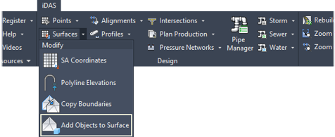
Location on Compact Ribbon:
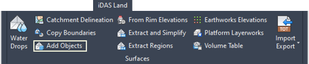
Location on Extended Ribbon:
Procedure
1. Choose where the objects come from
In the Drawing Objects group, select one of the two sources:
- Model space. Click the select button, then pick the objects in the drawing. The prompt reads
Select lines, polylines, 3d polylines, AutoCAD points, COGO points or 3d faces:. The label beneath the button reports the count, for example24 drawing objects selected. - From drawing:. Click
...and browse to a DWG file. Every matching object in that drawing is used.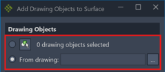
2. Filter the object types
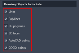
In Drawing Objects to Include, clear any type you do not want to use. All six are selected by default:
- Lines
- Polylines
- 3D polylines
- 3D faces
- AutoCAD points
- COGO points
The filter applies to both sources, so it is the only way to narrow down what is taken from an external drawing.
3. Decide how the triangulation is built
In Options, set Maintain edges from objects:
- Selected, the vertices are added together with the edges between consecutive vertices, so the surface follows the geometry of the source objects. Use this when the objects already describe the triangulation, such as 3D faces or breakline-style linework.
- Cleared, only the vertices are added, duplicate points are discarded, and Civil 3D triangulates them freely.

4. Choose the target surface
In the Surface group, set Surface: to either an existing TIN surface or the create entry:
- To add to an existing surface, select it. Name: and Style: then follow that surface.
- To create a surface, select the create entry, type a Name: and choose a Style:. The name must be a valid Civil 3D name and must not already be in use.

5. Run the command
Click OK. A progress meter reports Processing points and, when edges are not maintained, Removing duplicate points. You can interrupt either stage, which cancels the whole operation.
Expected result
The selected vertices are added to the target surface, or a new TIN surface with the name and style you supplied is created and the vertices are added to it. The drawing regenerates, so the surface is redrawn with its style immediately. With Maintain edges from objects selected, the surface triangulation follows the edges of the source objects; otherwise the points are triangulated by Civil 3D. Your source selection mode, object type filters, edge option, surface and style are remembered for the next run.
Troubleshooting
No lines, polylines, 3D polylines, 3D faces, AutoCAD points or COGO points have been selected
Model space is the chosen source but nothing was picked. Click the select button, select at least one supported object, then click OK again.
No drawing selected
From drawing: is the chosen source but the path is empty. Click ... and browse to a DWG file.
The surface name contains invalid characters
Civil 3D rejected the surface name. Remove characters that are not allowed in a Civil 3D object name, such as <, >, /, \, ", :, ;, ?, *, |, ,, = and the backquote.
The surface name is already in use
A surface with that name exists in the drawing. Enter a different name, or select the existing surface in Surface: and add the objects to it instead.
Nothing is added to the surface
Every selected object was filtered out. Check that the type of object you selected is still selected in Drawing Objects to Include.
The surface does not follow the linework
The vertices were added without their edges. Re-run the command with Maintain edges from objects selected.